Arduino Master Modbus RTU & PLC Panasonic RS232
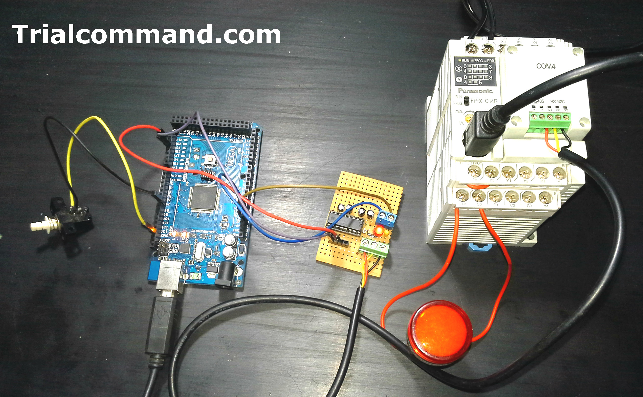
We decided to perform a test with an industrial component, as we have a panasonic PLC with which we have already done previous tests of modbus communication. In this case our Arduino Mega 2560 R3 will be configured as Master Modbus RTU via RS232 will communicate with the PLC configured as Slave Modbus RTU.
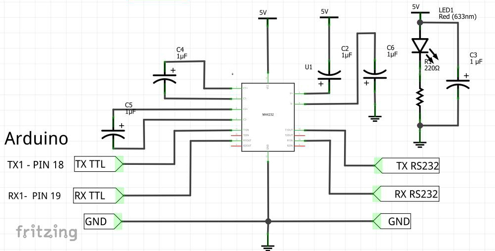
Since arduino handles TTL voltages 0 -5v we have manufactured a MAX232 TTL to RS232 converter, quick view of MAX232 DIY board, We have taken 5v to power the MAX232, although we recommend using an external 5v source and unify earth.
References
Tests
The Arduino board will read 2 PLC potentiometers and the activation of a light pilot.
The test will use 3 modbus communication registers between Arduino and PLC configured as follows:
- An NA pushbutton connected to the Arduino digital input assigned to the Holding Register [4] activates the output to Relay Y0 which has a light pilot connected.
- Potentiometers V0 of PLC assigned to Holding Register [0], to be displayed on the Arduino serial terminal.
- Potentiometers V1 of PLC assigned to Holding Register [2], to be displayed on the Arduino serial terminal.
Arduino Master Modbus RTU RS232 & PLC Panasonic Slave
Connections
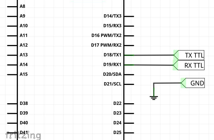
Arduino Mega 2560 R3 – Port Serial1
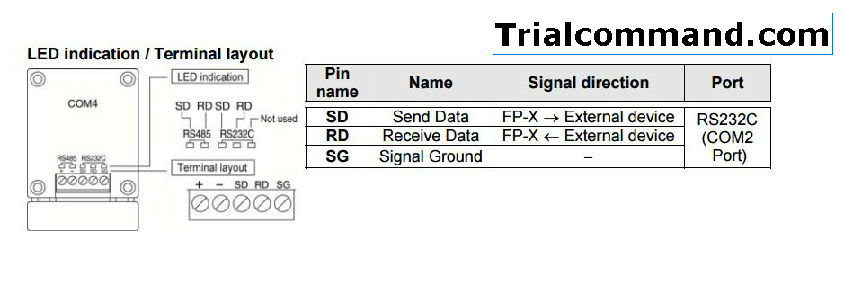
Cassete COM4 – COM2 Port Serial RS232
Conclusions
- The board of Arduino controls without any inconvenience the PLC, you only have to consider communication parameters, speeds physical connections, wiring, etc.
- Easily this application, in this case a PLC in more practical cases data solutions or control with meters, counters and PID controllers.
- We recommend not to use speeds higher than 9600, if it works at 115200 but we want to guarantee security in the transmission given the Arduino and max232.
References
Downloads
- Strategy FPWIN-Pro PLC Panasonic Slave Modbus
- Arduino Master Modbus RTU Library
- Example Arduino Master Modbus RTU